Troubleshooting Manual
Warning! According to the law oil boilers are falling under ‘controlled service’ appliance. In practice it means that your boiler needs to be installed and commissioned by a person having proper qualifications (Oftec registered technician)
Before using the boiler, after each restart and repair following steps should be considered
- examine the flue terminal , make sure it is not damaged or blocked
- start boiler to verify correct operation of its control system
- examine all fuel and water system connections and fittings
- examine all joints and verify the tightness of all fittings that may leak in the future
- verify expansion vessel air charge
- verify if the system pressure is set at the right levels, where not refill, vent and re-check the system
- examine all ventilation openings, those need to be right size and its opening needs to be clear
- remove water/sludge extend from the fuel tank. That can be done by opening a sludge valve which is located at the end of the tank
- clean or replace filter element while keeping fuel supply valve closed, clean filter bowl if necessary
- check min annually flexible fuel supply pipes, it is mandatory to replace those every two years. Whenever in doubt replace the pipes
Safety first!
Warning! Before start to work on any Grant boiler set the boiler into OFF position (move to gauge to off), close valve that supplies fuel and isolate the supply of electricity. Wait till the boiler cools down. Take a note of what fuel is suppose to be used (label on the inside of case side panel). Certain repairs needs to be obtains due to wrong fuel used. You need to pay special attention to:
- avoiding any skin contact with mineral oil or/and with clothes contaminated with fuel. In instances where oil contacted skin wash it with soap, use a lot of rinsing water (until oil is fully removed from skin ) and a lanolin-based barrier cream afterwards
- avoid any cloth contact with mineral oil, especially those which are touching your skin directly, avoid puting oily rags or tools in pockets, especially trouser pockets
- always have a first-aid treatment near the place you work
- avoid inhaling any vapours from mineral oils
- never hang or put anything next to or on a boiler itself
- all repairs, service and maintenance work (under or over guarantee) must be carried out only by an authorized boiler technician using Grant original spare parts
- boiler should be immediately switched off you you suspect that it is not working properly
How to adjust temperature of the water for heating or/and hot water? Boiler thermostat/heat exchanger usage.
The boiler thermostat has set to operate at a range 75°C – 85°C. We recommend to set the temperature to maximum in order to assure optimal hot water supply. To ensure that the hot water performance is not reduced first thing in the morning, or in the evening if the heating is off through the day, set the heating timer to switch the heating on at least 30 minutes before hot water will normally be required in the morning (or evening).
Attention! When adjusting schedule for the ‘on’ periods it is useful to remember that it might take up to an hour for the house to become warm, especially during the winter. Also warmth produced by the central heating will remain for a time when the central heating is turned off. Whenever you will need central heating actually working during normal ‘off’ periods, set the heating switch to “constant” position. Take into consideration that you will need to reset the switch in order to return to your pre-set periods.
1.Store switch can be used to manually turn off hot water produce is not needed. When the store switch is set to OFF position, the burner will not fire in order to maintain the water temperature. The hot water (store) pump won’t operate either.
2.Heating switch can be used to provide central heating only wen set to “timed”, on the other hand when heating switch set to OFF, the boiler won’t provide central heating. You can also use “constant” option and then boiler will provide central heating continuously, over-ruling all of the other settings.
3.Boiler on/off switches can also be used for setting heating or/and hot water. The internal timer (if fitted) will operate with the on/off switch set to OFF whenever electric supply is provided to the boiler, but the boiler won’t operate to provide hot water.
4.Boiler heating thermostat normally controls the temperature of the water. It’s primarly funtion is to lead the central heating system. Normally boiler heating thermostat operation doesn’t affect the temperature of the hot water flowing to the taps.
The temperature of the water leaving the boiler to the radiators can be increased by turning the boiler (heating) thermostat clockwise. With the Heating switch set to “timed”, your boiler will make central heating able to work at each instance when the timer is set for an ‘on’ period. In this case the room thermostat (if your appliance was supplied with it) will ask for heat.
For summer time operation, when central heating is not required, set the heating switch to”how water only” position or “off” in case of Vortex Combi
How to re-pressurise the system by adding water?
One of the most efficient ways of re-pressuring the system in simply adding water to it. Whenever water pressure falls down (in yourthe heating system) under the value of 0.2 bar your appliance will activate automatic special function called cut-out switch for too low pressure. You will recognize it by seeing amber light illuminating. The system will need be recharged to values somewhere between 0.5 and 1 bar. In instances where your the heating system loses pressure frequently you should inform your installer in order to investigate the possible cause. When refilling the system following precautions need to be taken care of:
– add water to the system only when the boiler is off and the system it is cold, pay attention no to overfill
– make sure a flexible filling loop is properly connected, ensure that open position of flexible filling loop to the boiler. Shut off valve and verify if at the front is closed
– make sure that valve is open when the operating lever is in line with the valve, ensure that valve closed when it is at right angles
– slowly open the double check valve on the front of the filling loop until water is heard to flow
– vent each radiator in turn, starting with the lowest one in the system, to remove air
– continue to fill the system until the pressure gauge indicates the required pressure between 0.5 and 1.0 bar. Close the fill point valve
– close the valves either side of the filling loop and disconnect the loop.
How to reset burner lock out?
Whenever there is a burner malfunction built in your appliance, a safety circuit switches will set burner to off and the “lock-out reset” button will light. Normally those malfunctions are short lived. In those instances reset button will bring back normal operation. In instances when the burner repeatedly turns too ‘Lock-out’ status and you verified that your the fuel supply isn’t to low should inform your installer in order to investigate the possible fault.
How to reset overheat thermostat?
Your boiler is equipped with a safety overheat thermostat. The overheat thermostat will automatically switch off the boiler in the case of a control malfunction causing overheating. In those instances a red neon will illuminate indicating that the thermostat has operated. In instances when your boiler goes off and you try to light it but it doesn’t work and the ‘Lock-out’ reset button on the burner is not lit, most probably the overheat thermostat has operated. The boiler will not light until the thermostat is reset. To reset, unscrew the small plastic cap press the button then replace the cap.
Attention! Wait till the boiler to cools down before the button will reset. If this condition repeats often, inform your installer in order to investigate the possible fault.
Ventilation
Boiler needs to have a proper ventilation. All ventilation openings must be clean and clear. You should periodically verify it and clean as needed. Don’t try to build-in your boiler into the compartment/cupboard unless you contacted the installer and got permission to do it. Don’t place any combustible material around flue pipe or on the boiler.
The flue terminal
The flue terminal that is located on the outside wall can’t be damaged or obstructed. Pay special attention to the flue terminal not getting blocked by large piles of snow during the wintertime.
Frost protection
Some Grant boiler models come equipped with a frost thermostat. Check if your appliance is equipped with frost protection (optional), whenever it is not the case it is recommended to leave the boiler on with the boiler thermostat set at a low setting, instead of switching off the boiler. For periods longer than a few months we recommend system draining. Draining should be performed by qualified boiler specialist.
Cleaning and servicing
For everyday cleaning simply use a dry cloth. No special material needed. To remove difficult marks and stains, use a wet cloth first and then and finish with a dry cloth. Don’t use abrasive pads or cleaners.
Your boiler should be serviced annually in order to make sure it is safe and operates efficiently. Contact your installed to agree on a service date.
Electric supply failure
The boiler won’t operate, where there is no electric supply. Your boiler will relight automatically when electric supply is restored. Grant boilers require a 230/240 V ~ 50 Hz power supply and it needs to be protected by a 5 Amp fuse. Attention!This appliance must be earthed.
Note: The time on the internal 7-day or 24-hour timer may need to be reset after a power failure.
Error codes
All Grant oil fired boilers are designed to heat up water directly from the main water supply at your home. Not all Grant oil fired boilers are suitable for use with a sealed system, check if that is the option on your user manual. The maximum temperature of the central heating water is 85°C for the Combi V3 and Combi Max and 80°C for the Vortex Combi models. We advice to you check through the following guide tables when identifying problems and for the purpose of correct communication with customer service representative or requesting a service engineers visit. In instances where the problem found be other than with the appliance Ideal service engineer will a charge for the visit if your boiler is out of warranty period.
Table A – boiler start and burner related fault finding table for all Grant Vortex oil fired boilers
| Fault | Cause | Action |
|
Boiler will not start
|
Low pressure cut-out activate | Refill system to 0.5 – 1.0 bar. |
| no electrical supply to burner | Check for 230 V at boiler terminal block. | |
| check controls are switched on and calling for heat | Check boiler On/Off switch is set to ‘ON’ | |
| overheat thermostat has operated | Set boiler thermostat to maximum. | |
|
Boiler thermostat and/or overheat thermostat faulty
|
Set 3-position Heating switch to ‘Constant’ | |
| Check and reset thermostat as necessary | ||
| Check for 230 V output from BURNER LIVE terminal of PCB. | ||
| Check continuity of overheat thermostat – replace as necessary | ||
|
Burner lights but goes to lock-out
|
fault with burner.
|
Press reset button – no more than twice. |
| If burner does not operate refer to burner fault finding chart | ||
|
Burner not lighting, oil & electricity present at burner
|
No fuel supply | Check tank and refill as necessary |
| Oil tank empty | Check and open valves as necessary | |
| Isolating valve(s) in fuel supply line closed | Check and reset as necessary. | |
| Fire valve closed |
Check and clean as necessary
|
|
| Fire valve closed.Fuel line filter is blocked | ||
| Oil supply line is air locked | Vent oil supply line at pump. | |
| Excessive combustion air |
Reset burner air damper and check combustion
|
|
| Fault with burner. | ||
|
Burner fires but smoke visible from flue or high smoke number
|
Insufficient combustion air supply to burner
|
Check flue terminal is clear (balanced flue). |
| Check room ventilation is adequate (conventional flue). | ||
| Check condition of burner fan | ||
| Check air damper setting on burner. | ||
| Incorrect or faulty nozzle fitted. | Check nozzle size and type and replace if necessary | |
| Fuel pressure too high. | Check fuel pressure and adjust as necessary | |
| Burner pulsates | Insufficient combustion air supply to burner | Check as for high smoke number (above) |
|
Burner cycles On and Off
|
Contaminated combustion air (balanced flue). | Check the flue terminal is unobstructed |
|
Insufficient oil flow to burner due to restriction in supply line.
|
Connect vacuum gauge to pump and check pump vacuum. | |
| Check for blockage in filter, fire valve, valves or pipe and rectify | ||
| Excessive combustion air. | Reset burner air damper and check combustion. | |
|
Fumes and puffing on starting
|
Flue is blocked | Check flue is clean and unobstructed – rectify as necessary |
| Insufficient flue draught. | Check flue draught and improve flue as necessary. | |
| Flue pipe or liner is too large or existing stack is unlined. | Check flue condition/size and alter as necessary. | |
|
Insufficient combustion air supply to burner.
|
Check as for high smoke number (above) | |
| Check that an extract fan is not pulling combustion gases from burner | ||
|
Flame slow to stabilise on starting
|
Insufficient combustion air supply to burner.
|
Check as for high smoke number |
| Check nozzle size and type and replace if necessary | ||
| Fuel pressure too low. | Check fuel pressure and adjust as necessary |
Table B – oil /combustion smells and thermostat related fault finding table for all Grant Vortex oil fired boilers
| Fault | Cause | Action |
| Oil smells | Oil leak in supply line or burner | Check all joints and flexible hose for leaks |
|
Combustion fume smells
|
Leak around boiler cleaning door | Check gasket, re-tighten nuts or replace gas |
| Burner not correctly fitted on mounting flange | Remove and re-fit burner ensuring correct fitting | |
| Burner seal ‘O’ ring damaged or missing. | Check and replace ‘O’ ring as necessary | |
| Leakage around flue connection. | Check and re-seal flue as necessary | |
|
Overheat thermostat operating
|
Faulty boiler thermostat | Check and replace as necessary |
| Thermostat sensor not connected to PCB (Vortex Combi only) | Check and rectify as necessary. | |
| Faulty overheat thermostat. | Check and replace as necessary. |
Table C – water and temperature related fault finding table for all Grant Vortex oil fired boilers
| Fault | Cause | Action |
|
No water flowing from hot tap
|
Mains water supply is not connected to cold water inlet of boiler | Check and rectify as necessary. |
| One or more isolating valves, stop cocks, etc. in the pipework are closed | Open all valves in pipework to and from boiler. | |
| The cold water isolating valve in the boiler is closed. | Open valve (situated above pump in front of boiler) | |
| There is a blockage (or blockages) in the pipework. | Check and rectify as necessary. | |
|
No hot water operation
|
Hot tap is not connected to hot water outlet of boiler | Check and rectify as necessary. |
| Insufficient flow of water through boiler | Check flow is at least 3 litres/min – rectify as necessary. | |
| Boiler cold water and hot water connections reversed. | Check and rectify as necessary. | |
| Thermostatic mixing valve incorrectly fitted | Check hot and cold inlets are connected correctly. | |
|
Pump is not operating in hot water mode.
|
Check operation of diverter valve | |
| Check pump is free to rotate and is vented. | ||
| Check for 230V supply to pump | ||
| Check electrical continuity of pump microswitch | ||
| Check wiring continuity from pump to microswitch. | ||
| Diverter valve microswitch(es) faulty | Check switch continuity, replace if faulty | |
| Diverter valve microswitches not operated | Check diverter valve diaphragm. | |
| Diverter valve seized | Remove, dismantle and clean. | |
| Diverter valve diaphragm failed. | Replace diaphragm or complete diverter valve. | |
|
Low water temperature at tap
|
Flow of water through boiler too high | Reduce flow and check water temperature. |
| Boiler thermostat incorrectly set | Set boiler thermostat to maximum | |
| Thermostatic mixing valve incorrectly set | Set mixing valve to setting ‘4.5’. | |
| Faulty boiler thermostat | Check continuity and replace if necessary | |
| Pump speed setting too low | Set pump speed switch to maximum (top position) | |
| Pump is incorrectly fitted | Check and rectify as necessary. | |
|
Hot water for short period only
|
Burner not firing for hot water (after a short time)
|
Check operation of burner on central heating |
| Check electrical continuity of burner microswitch | ||
| Check electrical continuity of thermostat | ||
| Check operation of diverter valve. | ||
| Check wiring continuity from burner to microswitch | ||
| Burner oil pressure set too low at oil pump | Check and set oil pressure to correct value | |
| Incorrect oil nozzle fitted to burner | Check and fit correct nozzle | |
|
No operation on heating
|
Timeswitch either not set, or not in an ‘ON’ period | Check setting and set to ‘Constant’ to test |
| Timeswitch not operating | Check power supply to timeswitch | |
| Faulty timeswitch | Check and replace if necessary | |
| Faulty timeswitch switch contacts | Check continuity of switch, replace if necessary | |
| Timeswitch OK but not switching boiler on | Check continuity of wiring to timeswitch. | |
| Heating switch set to ‘HOT WATER ONLY’ | Check and set switch to ‘Constant’ to test. | |
| Room thermostat not calling for heat | Set thermostat to call and check boiler operates | |
| Faulty room thermostat | Check continuity of thermostat, replace if necessary | |
| No room thermostat or external timeswitch connected to boiler | Check link fitted between 8 & 9 on boiler terminal block | |
|
Flow temperature low
|
Boiler thermostat is set too low | Check and reset as necessary |
| Boiler thermostat faulty | Check and replace if necessary | |
| Boiler is underfired | Check nozzle size & fuel pressure, correct as necessary | |
| Combustion setting of burner incorrect. | Check settings and correct as necessary | |
| Boiler heat exchanger is sooted up | Check boiler & baffles and clean as necessary |
Domestic hot water system
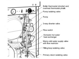
To maintain a longer and more consistent hot water temperaturethe factories fitted a flow restrictor to all Grant models (Vortex Combi 36 and Combi Max are the only exceptions) The purpose of flow resistor is to reduce the flow rate to 15 litres/min. You can find flow restrictor inside of the cold water inlet of the isolator valve (placed on the outside of it). To ensure proper operation water pressure from incoming mains should be at the 1-8 bar level. In instances when pressure exceeds 8 bar reducing pressure valve usage is recommended.The boiler may still operate down to a pressure of 1.0 bar but with a reduced flow rate. The minimum flow rate needed for the flow switch to operate is 3 litres/min.
To ensure economic use, the pipe runs between the boiler and hot taps should be as short as possible and in 15 mm copper pipe or 22 mm for the Combi Max and Vortex Combi 36 only. Where possible the pipework should be insulated to reduce heat loss. All taps and mixing valves used in the domestic hot water system must be suitable for operating at a mains pressure of up to 8 bar.
When required, a shower may be fitted in the domestic hot water system. It is recommended that thermostatically controlled shower valves are used to protect against a flow of water at too high a temperature. in the situations where fixed head type shower is used, no anti-syphonage devices are required. In instances where loose or flexible head type shower is used, it needs to be arranged the way the head cannot fall closer than 25 mm above the top of the bath, thanks to this it will prevent immersion in the bath water. If not possible, an anti-syphonage device should be fitted at the point of the flexible hose connection.
Attention! Hard Water
A water hardness test kit is supplied with the boiler. Whenever total hardness of the water supply exceeds 125 ppm, an in-line scale inhibitor should be installed in the cold water supply to the boiler.
Repair and replacement parts
Before you start to work on Grant boilers set the boiler into OFF position (move to gauge to off), close valve that supplies fuel and isolate the supply of electricity. Wait till the boiler cools down. Take a note of what fuel is suppose to be used (label on the inside of case side panel). Each time conduct all electrical check: resistance, polarity and continuity before and after any work
Circulating pump replacement
1. Isolate the appliance
2. Gain General Access -unhook the expansion vessel from the front of the boiler and lay to one side.
3. Manually operate the safety valve on top of the boiler heat exchanger, to de-pressurise the boiler. You may or may not drain down the heating system.
4. Close the primary return isolating valve and the pump isolating valve as shown on the picture below
5. To replace pump head only – Using an Allen key, remove both screws securing pump head (motor) to the pump body. Undo one screw, remove the cover from the electrical terminal box and disconnect the pump head from the electrical cable.
6. Fit the replacement pump using the reverse of the above procedure, ensuring that the new gasket is correctly fitted between the pump head and body.
7. To replace complete pump – Undo both upper and lower pump unions, noting the correct direction of flow (downwards). Undo one screw, remove the cover from the electrical terminal box and disconnect the pump from the electrical cable.
Warning! Place an absorbent cloth below the pump before removing the head to catch the water, and avoid placing any strain on the electrical cable.
8. Fit a replacement pump using the reverse of the above procedure, ensuring the sealing washers are correctly fitted in the pump unions, and that pump flow direction (as indicated by arrow on pump body) is correct. Set the pump speed selector switch to maximum.
9. Open the pump isolating valve and the primary return valve, then refill the central heating system as described in section 5.2, checking for leaks.
10. Re-assemble in reverse order
Plate heat exchanger and diverter valve replacement
1. Isolate the appliance
2. Gain General Access -unhook the expansion vessel from the front of the boiler and lay to one side.
3. Unscrew and remove the single burner fixing nut (located above the burner, in the middle of the mounting flange) and withdraw the burner from the boiler and lay it to one side.
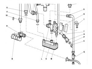
4. Close the cold water inlet isolating valve (A) as shown on the picture below
5. Manually operate the safety valve on top of the boiler heat exchanger to de-pressurise the boiler. You may or may not drain down the heating system.
6. Close the primary return isolating valve (B) and the pump isolating valve as shown on the picture above
7. Remove the spring circlip holding the microswitch (4) assembly to the diverter valve (1), and separate the microswitch assembly from the valve.
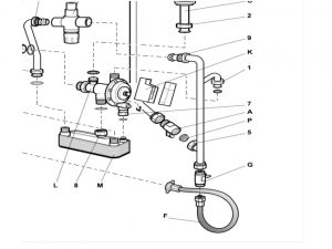
8. Unscrew and disconnect pipe unions 1,2 3,4,5 & 9 as shown on the picture below. Remove the vertical 15 mm pipe from the boiler to gain access to pipe union 6. Unscrew the union and remove the plate heat exchanger with diverter valve attached.
9. To separate the plate heat exchanger from diverter valve, unscrew the two union nuts 7 & 8 (look at the picture above)
10. Re-assemble in reverse order
Thermostatic mixing valve replacement
1. Isolate the appliance
2. Gain General Access -unhook the expansion vessel from the front of the boiler and lay to one side.
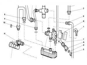
3. Unscrew and disconnect pipe unions 1, 5 & 9 as shown on the picture. Remove the vertical 15 mm pipe fromthe boiler.
4. Unscrew the two other unions 11 and 12 on the mixing valve, and remove valve from the boiler as shown on the picture
5. Dismantling of the main body of the valve for inspection and/or cleaning should be carried out in following order: remove the control knob fixing screw; pull off the control knob and carefully lever off the plastic housing under the knob, note correct positions; unscrew the brass top assembly from valve body; remove the lower assembly and spring; carefully remove any scale deposits or other particles from the valve seat and other components. Vinegar can be used to remove calcium, but take care not to scratch metallic surfaces. Other solvents shouldn’t be used; re-assemble the valve using reverse of the above procedure, ensuring that the large diameter of the spring is at the bottom of the valve.
6. Replace the mixing valve and re-assemble in reverse order.
Warning! Ensure that the mixing valve is correctly connected, i.e. with the Hot (H) inlet at the rear and the Cold (C) inlet at the front.
Expansion vessel replacement
1. Isolate the appliance
2. Gain General Access -unhook the expansion vessel from the front of the boiler and lay to one side.
3. Drain the central heating system and boiler using the drain cock on the boiler.
4. Unscrew the flexible hose union nut on the expansion vessel and disconnect the hose
Warning! Ensure the sealing washer inside the union is kept for re-assembly.
5. Slacken the two cross head screws and remove the mounting bracket from the expansion vessel.
6. Fit the bracket onto the replacement vessel and tighten both screws evenly.
7. Reconnect the flexible hose, ensuring that the sealing washer is correctly fitted in the union before tightening
8. Before filling and re-pressurising the heating system you should verify the charge pressure in the expansion vessel
using a suitable pressure gauge.
9. Re-assemble in reverse order and refill the central heating system
Automatic air vent replacement
1. Isolate the appliance
2. Gain General Access- unhook the expansion vessel from the front of the boiler and lay to one side.
3. Drain the central heating system and boiler using the drain cock on the boiler
4. Slacken the four control panel fixing screws, carefully disengage the control panel from both casing side panels and the front top panel and allow it to rest at an angle on its right hand end, to gain access to the Automatic air vent.
5. If a conventional flue is fitted to the boiler, unhook the flexible air inlet tube from the hook bracket on the crossmember, and remove the hook bracket from the boiler crossmember.
6. Using an adjustable spanner or grips, unscrew and remove the air vent.
7. Fit a replacement air vent using reverse of above procedure
8. Re-assemble in reverse order and refill the central heating system
Pressure relieve valve replacement
1. Isolate the appliance
2. Gain General Access -unhook the expansion vessel from the front of the boiler and lay to one side.
3. Drain the central heating system and boiler using the drain cock on the boiler
4. Slacken the four control panel fixing screws, carefully disengage the control panel from both casing side panels and the front top panel and allow it to rest at an angle on its right hand end
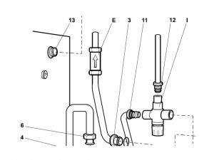
5. Working from the front of the boiler, disconnect the cold water inlet pipe at both the elbow connector in the top of the boiler, and at connection 5 on cold water inlet isolating valve (A) as shown on the picture below
6. Carefully move the pipe forwards and then down by about 100 mm to leave access to the two compression connections on the check valve.
7. Unscrew both compression nuts on the check valve and remove it from the boiler
8. Unscrew and disconnect pipe union 3 from the rear of the diverter valve. Allow the pipe to rest on top of the plate heat exchanger.
9. Unscrew the capillary tube nut and disconnect it from the valve
10. Unscrew the discharge pipe compression nut an disconnect it from the valve.
11. Unscrew the valve union and remove the valve from the boiler
12. Fit a replacement valve using the reverse of the above procedure, ensuring that the sealing washer provided is correctly fitted in the valve union before tightening.
13. Manually operate the relief valve to check it’s operation, then refill as above.Re-assemble in reverse order and refill the central heating system
14. Re-assemble in reverse order and refill the central heating system